1×7 Stainless Steel Wire Rope Product Introduction Overview: The 1×7 stainless steel wire rope is a high-quality, durable, and versatile wire rope constructed from a single strand of seven individual ...
See Details


Selecting stainless steel wire rope is not simply a matter of choosing a diameter. Two ropes with the same outside diameter can perform very differently because their construction, core, stainless steel grade, lay direction, and individual wire size are different.
For engineers, distributors, marine-equipment suppliers, architectural contractors, and industrial buyers, understanding specifications such as 1x19, 7x7, 7x19, 6x19, and 6x36 is therefore essential.
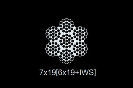
As a stainless steel wire rope manufacturer, JiangSu Kailong Stainless Steel Products Co., Ltd. recommends starting with the application: determine whether the rope must resist repeated bending, abrasion, crushing, corrosion, or primarily static tensile loading. The construction can then be matched to those requirements.
A wire rope is built in stages. Individual stainless steel wires are twisted together to form a strand, and multiple strands may then be helically laid around a center or core to form the finished rope.
This is what specifications such as 1x19 and 7x19 describe.
For example, 1x19 means one strand containing 19 wires, while 7x19 generally describes seven strands, with each strand containing 19 wires. Increasing the number of smaller wires generally improves flexibility, while using fewer, larger wires generally improves abrasion resistance and structural stiffness.
| Construction | Basic Structure | Relative Flexibility | Relative Abrasion Resistance | Typical Applications |
|---|---|---|---|---|
| 1x19 | 1 strand, 19 wires | Low | High | Guy wires, architectural cables, railings, standing rigging |
| 7x7 | 7 strands × 7 wires | Medium | Medium-High | Control cables, light rigging, general-purpose cable |
| 7x19 | 7 strands × 19 wires | High | Medium | Pulley systems, winches, flexible control cable |
| 6x19 Class | 6 outer strands, typically 19–26 wires per strand | Medium | High | Hoisting, general industrial rope |
| 6x36 Class | 6 outer strands, typically 27–49 wires per strand | High | Medium | Cranes, winches, repeated bending applications |
The term “class” is important for larger wire ropes. A 6x19 Class rope does not necessarily contain exactly 19 wires in every strand; commercial 6x19 Class constructions can contain approximately 19–26 wires per strand. Similarly, 6x36 Class constructions commonly contain 27–49 wires per strand.
For smaller stainless steel cables, 7x7 and 7x19 are frequently marketed in the United States as aircraft cable. However, the commercial term “aircraft cable” should not automatically be interpreted to mean that a cable is approved for aircraft flight-control use. Buyers should verify the applicable specification and certification for safety-critical aerospace applications.
A useful selection rule is:
Fewer, larger wires → stiffer rope and better abrasion resistance.
More, smaller wires → greater flexibility and better bending-fatigue performance.
This is why 1x19 stainless wire is widely suited to tension members and standing rigging, whereas 7x19 is normally preferred where the cable must repeatedly pass around pulleys.
In stranded wire ropes such as 6x19 and 6x36 constructions, the center of the rope plays an important mechanical role. Three commonly encountered core concepts are fiber core, wire strand core, and independent wire rope core.
A fiber core (FC) provides cushioning and flexibility and can retain lubricant. It is relatively lightweight, but it provides less resistance to crushing than a steel core.
An independent wire rope core (IWRC) is effectively a smaller wire rope located at the center of the main rope. It increases structural support, strength, resistance to crushing, and stability under high loading.
A wire strand core (WSC) uses a strand rather than a separate multi-strand rope as the center. It offers a steel-supported structure while remaining simpler than an IWRC configuration.
For heavy-duty hoisting, winching, multilayer drums, and environments involving high radial pressure, a steel core is often preferable. Fiber-core ropes may be appropriate when flexibility and lower weight are more important, provided the equipment and applicable standard permit them. OSHA, for example, specifically prohibits fiber-core rope for most crane boom-hoist reeving covered by its construction-crane rule.
The rope’s lay is another important specification.
With regular lay, the wires within each strand are twisted in the opposite direction from the strands around the core. Regular-lay rope is comparatively stable and has less tendency to rotate or untwist during handling.
With lang lay, the wires and strands run generally in the same helical direction. Longer sections of individual wires are exposed along the rope surface, which can improve abrasion resistance and flexibility, but the rope can have a greater tendency to rotate and should therefore be used only where the equipment and termination arrangement are suitable.
The lay may also be described as:
For general lifting systems where rotational stability and straightforward handling are priorities, regular lay is frequently selected. Lang lay can be attractive for applications involving significant abrasion and repetitive bending, but the complete rope system must be evaluated rather than selecting lay direction in isolation.
After construction, stainless steel grade is one of the most important purchasing decisions.
Both 304 and 316 stainless steel provide substantially better corrosion resistance than unprotected carbon steel in many environments, but they are not identical.
Type 304 is a chromium-nickel austenitic stainless steel and is widely used for general-purpose stainless wire rope in architectural, industrial, indoor, and moderately corrosive environments.
Type 316 contains molybdenum in addition to chromium and nickel. ASTM A492, which covers commonly used round stainless steel wire intended for stranding into wire rope, includes chemical-composition requirements covering elements such as chromium, nickel, and molybdenum as well as tensile requirements.
The molybdenum addition makes 316 significantly more resistant to localized corrosion, particularly pitting and crevice corrosion in chloride-containing environments.
That distinction becomes important in applications such as:
| Environment | Typical Recommendation |
|---|---|
| Indoor architectural cable | 304 often sufficient |
| General outdoor railing | 304 or 316 depending on exposure |
| Coastal installation | 316 preferred |
| Marine rigging | 316 strongly preferred |
| Dock or marina hardware | 316 preferred |
| Swimming-pool environment | 316 generally preferable, but chemistry must be evaluated |
| Road-salt / deicing-salt exposure | 316 preferred |
| Food-processing equipment | 304 or 316 according to chemicals and sanitation requirements |
“Marine grade” should not be interpreted as “corrosion proof.” Even 316 stainless steel can suffer staining, pitting, crevice corrosion, or stress-corrosion problems under sufficiently aggressive chloride concentrations, high temperatures, stagnant crevices, or chemical exposure.
Where additional surface protection or handling characteristics are required, stainless steel wire rope can also be supplied with PVC, nylon, or other polymer coatings.
PVC coating is economical and useful where surface protection, visibility, or isolation from surrounding components is required. Nylon coatings generally provide better abrasion performance and can be advantageous for control cables or applications involving frequent movement.
Coatings should not be used as a substitute for selecting the correct stainless steel grade underneath.
One of the most common specification mistakes is treating breaking strength and working load limit as interchangeable.
They are not.
Minimum breaking strength or minimum breaking force represents the specified force at which a new rope is expected to meet the relevant breaking-load requirement during testing.
Working Load Limit (WLL) represents the maximum allowable load for a particular working configuration after the required design factor, termination efficiency, operating conditions, and applicable regulations have been considered.
A simplified illustration is:
Breaking strength = 10,000 lb
If the applicable engineered system uses a 5:1 design factor:
10,000 ÷ 5 = 2,000 lb
The resulting 2,000 lb figure illustrates the design-factor concept, but buyers should not automatically calculate every rope’s WLL by dividing breaking strength by five. Required design factors vary according to equipment, rope type, application, regulations, reeving configuration, and manufacturer requirements. OSHA’s crane regulations, for example, prescribe specific design-factor requirements for certain rotation-resistant wire ropes.
For procurement, request a manufacturer’s breaking-strength table that matches all of the following:
diameter + construction + material grade + core type + rope specification.
Do not use the breaking strength of a 1x19 rope to approve a 7x19 rope simply because both have the same nominal diameter.
Diameter must also be inspected correctly. Measure across the rope’s widest outside dimension, rather than measuring between two valleys in the strand pattern. Compare the measured value against the applicable product specification and manufacturer’s stated tolerance.
Relevant specifications may include ASTM A492 for stainless steel rope wire, together with appropriate ASTM, ISO, DIN, equipment-manufacturer, or application-specific rope standards. ASTM A492 specifically addresses stainless steel wire intended for stranding into wire rope rather than acting as a universal finished-rope approval standard.
For receiving inspection, purchasers should confirm:
Correct rope selection can still be defeated by incorrect installation.
For U-bolt wire rope clips in applications where their use is permitted, the U-bolt goes over the dead end and the saddle rests on the live, load-carrying side. OSHA guidance also states that the clip manufacturer’s recommendations should determine the number of clips, spacing, and torque, and that clips should be tightened evenly and checked after the initial load is applied.
Do not apply one universal clip spacing or torque value to every rope diameter.
Swaged sleeves, sockets, thimbles, and other terminations should likewise be matched to the wire-rope diameter and construction and installed according to the fitting or rope manufacturer’s instructions. OSHA specifically requires socketing covered by its crane rule to follow manufacturer instructions.
Bending is another major service-life factor. Every time a rope passes over a sheave, the wires repeatedly bend and straighten. A pulley that is too small can dramatically increase bending fatigue. The required D/d ratio—sheave diameter divided by rope diameter—depends on construction and application, so the equipment or rope manufacturer’s minimum should be followed rather than assuming one universal bend radius.
Inspection should look for:
For construction cranes governed by OSHA 29 CFR 1926.1413, a competent person must begin a visual wire-rope inspection before each shift in which the equipment is used. OSHA also requires documented monthly inspections and a comprehensive inspection at least every 12 months.
Under that specific crane standard, examples of listed deficiencies include six randomly distributed broken wires in one rope lay or three broken wires in one strand in one rope lay for running rope, a diameter reduction greater than 5% from nominal diameter, a broken strand, significant corrosion, birdcaging, crushing, or evidence of core failure.
These numbers should not be treated as universal retirement limits for every stainless steel cable application. Sling, elevator, marine, architectural, aircraft, crane, and machinery applications can be governed by different standards. Always apply the most relevant equipment standard and manufacturer’s retirement criteria.
The fastest way to specify stainless steel wire rope correctly is to define the application before selecting a catalog number.
Provide the required diameter, construction, stainless grade, core, lay, minimum breaking force, operating environment, end termination, and whether the rope runs over sheaves or drums.
For example, a static architectural tension cable may favor a relatively stiff 1x19 construction, whereas equipment requiring repeated bending may benefit from 7x19 or a flexible 6x36 Class construction. Coastal exposure may move the material choice from 304 toward 316 even when the mechanical requirements remain unchanged.
JiangSu Kailong Stainless Steel Products Co., Ltd. can assist buyers in comparing stainless steel wire rope specifications for different industrial, architectural, marine, and general-purpose applications.
Contact us to request a stainless steel wire rope construction and breaking-strength table, or send your required diameter, load, working environment, and construction so the specification can be reviewed before ordering.
The first number generally identifies the number of strands, while the second describes the wires or construction class within those strands. A 1x19 cable contains one 19-wire strand, while a 7x19 cable normally contains seven strands of 19 wires each. A 6x36 Class rope has six outer strands and typically uses 27–49 wires per strand rather than requiring exactly 36.
7x7 stainless steel cable is commonly marketed as aircraft cable in the U.S., particularly for general control and utility applications. However, the commercial name does not by itself certify a cable for safety-critical aircraft use. Required aerospace specifications must be verified separately.
Choose according to loading, crushing, flexibility, temperature, and equipment requirements. Fiber cores provide flexibility and cushioning, while an IWRC provides greater structural support and resistance to crushing. Heavy-duty hoisting commonly favors steel-core constructions.
316 is generally the better choice where saltwater spray, chloride contamination, deicing salts, or coastal exposure are expected. 304 remains widely used for indoor, architectural, and less aggressive environments.
In regular lay, the individual wires and strands are laid in opposite directions, producing relatively good structural stability. In lang lay, they run in the same general direction, offering advantages in flexibility and abrasion behavior but generally creating a greater tendency to rotate.
A design factor can be used conceptually by dividing minimum breaking strength by the required factor. For example, 10,000 lb divided by five equals 2,000 lb. However, the applicable design factor must come from the equipment manufacturer, rope manufacturer, engineering requirements, or governing standard; 5:1 is not a universal rule. OSHA requires application-specific design factors in certain crane systems.
Inspection frequency and retirement criteria depend on the application. Look for broken wires, corrosion, abrasion, crushing, kinking, birdcaging, diameter loss, damaged terminations, and core failure. For construction cranes covered by OSHA 1926.1413, inspections include shift, monthly, and annual/comprehensive requirements, with specific removal and evaluation criteria.
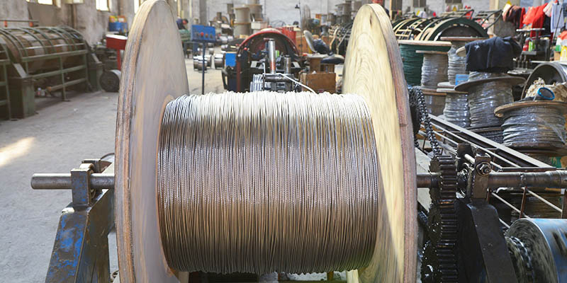
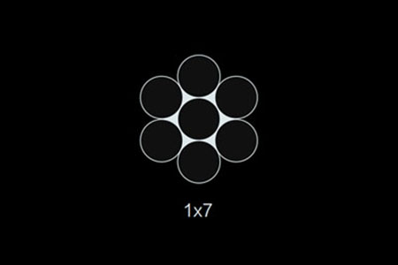
1×7 Stainless Steel Wire Rope Product Introduction Overview: The 1×7 stainless steel wire rope is a high-quality, durable, and versatile wire rope constructed from a single strand of seven individual ...
See Details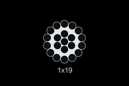
1×19 Stainless Steel Wire Rope Product Introduction Overview: The 1×19 stainless steel wire rope is a robust and high-strength wire rope made from a single strand of 19 individual wires twisted togeth...
See Details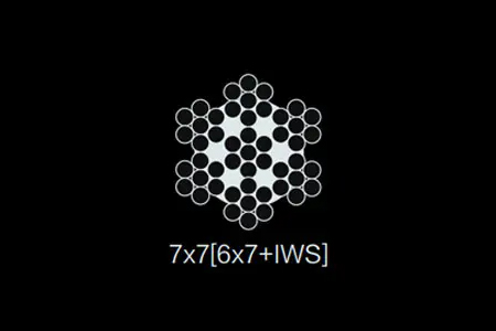
7×7 Stainless Steel Wire Rope Product Introduction Overview: The 7×7 stainless steel wire rope is a versatile, durable, and flexible wire rope made from seven strands, each containing seven individual...
See Details
7X19 [6x19+IWS] Stainless Steel Wire Rope Product Introduction Overview: The 7X19 [6x19+IWS] stainless steel wire rope is a high-performance wire rope designed for applications that require maximum st...
See Details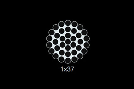
1×37 Stainless Steel Wire Rope Product Introduction Overview: The 1×37 stainless steel wire rope is a high-strength, durable wire rope made from a single strand of 37 individual wires twisted together...
See Details
6×7+FC Stainless Steel Wire Rope Product Introduction Overview: The 6×7+FC stainless steel wire rope is a high-quality wire rope designed for applications requiring both strength and flexibility. This...
See Details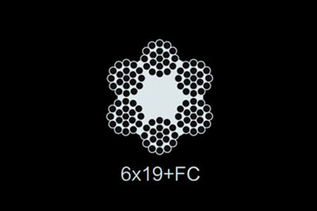
6×19+FC Stainless Steel Wire Rope Product Introduction Overview: The 6×19+FC stainless steel wire rope is a high-performance, versatile rope designed to provide exceptional strength, flexibility, and ...
See Details
19×7 Stainless Steel Wire Rope Product Introduction Overview: The 19×7 stainless steel wire rope is a high-performance wire rope designed for a wide range of applications requiring both strength and f...
See Details




 wechat scan